Porosity in Pressure Die Casting and How To Control It
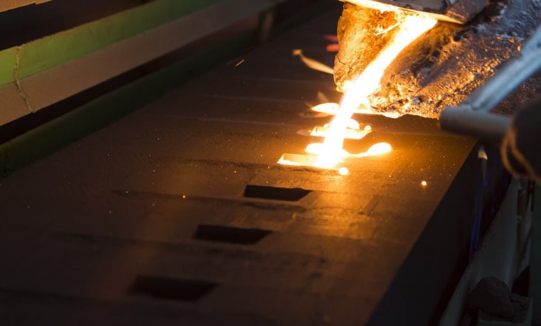
Pressure die casting is the quickest and most savvy method for making high volumes of parts in aluminum, zinc, or magnesium. Die casting parts have fantastic surface completions, keep up with reliable elements. And resistances. And waste minimal unrefined substance. Pressure die casting utilize to make motor squares and engine lodgings, apparatus parts, heat sinks, fittings, sections. And bunch other normal modern and business items. Explore pressure die casting manufacturers
Assuming you are fostering an item and considering pressure die casting for an undertaking. You ought to know that all cast parts should battle with the issue of porosity. It is unavoidable however it is controllable. To relieve the impacts of porosity in your parts. We should see what makes it and how utilize best plan practices to oversee porosity for prevalent outcomes.
What is porosity?
Porosity alludes to an opening or void in a generally strong cast metal part. Pores can go in size from tiny (micropores) to bigger voids quantifiable in cubic millimeters or bigger. Pores are not generally roundabout in cross-area but rather can likewise appear as unpredictable straight breaks.
Porosity has two fundamental driver:
cementing shrinkage and gas porosity. We should look all the more carefully at the underlying drivers for these two kinds and afterward we’ll propose methodologies to manage them.
Hardening Shrinkage
After liquid metal is infused into a form hole it starts to harden when it contacts the somewhat cooler dividers of the apparatus. This cementing makes the metal therapist. However, the rate at which this happens will fluctuate contingent upon the math of the shape apparatus and the kind of amalgam utilize. The semi-liquified piece of metal further away from the instrument divider calls slush. And it’s this region where pores are bound to frame. Furthermore, as the liquid metal turns into a strong it might obstruct the entry of fluid to different spots in the form. This can make pores by forestalling full liquification of all elements of the plan.
Gas Porosity
Gas pockets structure in a couple of ways. On account of aluminum. Hydrogen might drop out of suspension and make up for shortcomings with hydrogen gas. There likewise might air catch inside the form apparatus that not completely clear as the pit filled. This caught air call entrain. At long last, different fluids might get blend in with the liquid metal during infusion. These may shape discharge specialists. Released water powered liquid or even climatic stickiness. Any of these can quickly disintegrate and shape gas bubbles. Fluids or oils that don’t vanish become foreign substances that might shape incorporations in the last part.
Three Types of Porosity
We’ve recently taken a gander at the two significant reasons for pores: hardening shrinkage and gas porosity. In the two cases, pores might create that structure one of three significant sub-classifications. Cutaway perspective on visually impaired, through and encased pores in PDC. Delineation of visually impaired, through and encased pores.
1. Blind Porosity
The pore begins at the outer layer of an element and finishes someplace inside the body of the metal. These sorts don’t for the most part influence mechanical strength yet they might welcome erosion. It’s feasible to seal these pores subsequent to projecting. Particularly assuming the part needs to hold strain, for example, in pressure driven chamber.
2. Through Porosity
The pore begins at the surface and makes a channel the entire way through the element. And out the contrary divider. This causes a break and would should fix from the two sides.
3. Completely Enclosed Porosity
These pores exist inside the body of the metal and are not presented to the external except if they are subsequently entered during post-machining. The presence of such pores is ordinarily not evident except if the part is dependent upon a processed tomography examine subsequent to projecting or on the other hand assuming that the part is cut open for analytic reasons.
Suitable Tolerances for Porosity
Porosity commonly represents a normal of 5% of the complete volume of the part. It is not reasonable to kill porosity yet rather to guarantee that it contains in those region where it’s not adverse to part capacity or appearance.
Programming demonstrating
Recreation of micropores in a PDC part. Picture politeness of Flow3D. Subsequently, when a plan drawing or CAD record create, these regions ought to plainly assign with a bunch of details and resistances for permissible imperfections, similarly as would be the situation with layered resiliences.
Determinations for porosity generally appear as:
Number of pores inside a given volume. Greatest allowed size per pore. And complete volume rate per part. Producers will then, at that point, utilize this data to tweak the embellishment boundaries in a like manner. This will mean taking into account porosity in a few less basic regions while forestalling it in others. There will forever be these compromises to think about so it’s ideal to consider them toward the start of a venture.
Indicative Tools for Porosity Analysis (die casting)
Displaying programming presently exists to help item planners and makers anticipate where porosity is probably going to happen. These models depend on modern investigation of many trim boundaries. For example, fill, form profile, divider thickness, abide times, temperatures, compound creation, and numerous others. Utilizing this data, item architects can further develop their shape plans likewise, while decays can likewise streamline their set-ups ahead of time instead of depending on expensive and timing devouring experimentation.
Instrument Design Tips for Porosity Prevention
There are some instrument configuration best practices that ought to be utilized to assist with forestalling the most widely recognize reasons for porosity.
Die casting: Divider Thickness
Issue
By a wide margin, the most well-known reason for porosity is inconsistent cooling of the part inside the pit, which is thusly a component of fluctuating divider thicknesses.
Arrangement
The least demanding and most catalyst method for forestalling this is to keep up with predictable divider thicknesses sooner rather than later. That is the occupation of the shape device fashioner. Numerous other significant contemplations, like the plan of managers, ribs, gussets, and different elements. Those are like those of plastic infusion forming.
Recoil Rate
Issue
The therapist rate is impacted by the liquefying temperature of the amalgam, the cooling time, and the cooling temp. On account of aluminum, which is by a long shot the most well-known pass on projecting material, the expansion of silicon can bring down recoil rates extensively yet just inside a specific compound rate. An excess of silicon can antagonistically influence the mechanical exhibition of the composite.
Arrangement
It’s best that the item designer works intimately with the strain die caster to examine choices for unrefined components dependent on the application and plan.
Entraining Issue
It is trying to totally eliminate entrained air from a form device, particularly for complex shapes that have numerous inner elements where air can catch.
Arrangement
There are a couple of techniques for alleviating entrained air. One is to further develop the shape apparatus plan so there are no sharp corners or pockets where air can’t get away. Additionally, more vents can add or the plan of the entryway/sprinter framework advanced to permit get away from courses for air. Changing infusion speed and strain might assist with venting however can unfavorably influence the part in alternate ways so this should be done cautiously.
Last Tip
At long last, projecting should possible in a climate loaded up with argon or another dormant gas. For this situation it ideal to examine this cycle with the producer from the get-go in the plan stage. When the casting done it is then important to figure out how to precisely quantify porosity in the completed part.
Innovation for Measuring Porosity
New strategies have been created to assist producers with recognizing and measure porosity that is undeniably challenging utilizing ordinary techniques, for example, visual assessment, pressure testing, or horrendous testing. One of the most encouraging figured tomography, or CT.
CT output of PDC porosity
Notice that the regions closest to the apparatus divider are sans pore. CT filter from Exact Metrology.
In this cycle, different powerful X-beam photographs take of the part and afterward consolidated to make a 3D guide of within the piece. This can utilize for constant cycle control just as for making virtual experiences which can help with improving mold apparatus plans. It is becoming vigorous and solid enough to qualify as a genuine metrology-grade estimation instrument and in addition to a symptomatic device.
How does machining influence porosity?
The skin of a die casting part is the most thermally stable region. It’s the initial segment to cement and shows almost no porosity inside the primary .5mm or more. Since pores happen in the more deeply segments of castings, machining processes like tapped and strung openings might open encased pores. A few castings should have the option to hold air or fluid tension. For example, for hydraulic chambers or manifolds. So these pores should fix in the wake of machining.
Fixing Pores with Vacuum Impregnation
It’s normal in the industry to apply vacuum impregnation to the outer layer of kick the bucket castings to successfully seal them.
This is for the most part a three-venture process:
When impregnated, the part eliminates from the chamber and the sealant completely restore. This view as a one-time, long-lasting surface treatment.
Read more: Wire Nail Machine


